MiniCNCBasics
Protospace Mini CNC User Basic Instructions:
These instructions are intended for the most basic of users. Note that using this CNC is fairly manual and requires an attention to detail and a willingness to experiment. Things are easily broken and you can (and probably will) do harm to the bit, machine, and possibly yourself if you do not pay attention, and above all else THINK.
Step 1 – Starting up the Computer and CNC
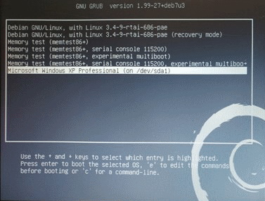
1. To run the Mini CNC, boot the PC into XP.
2. The Mach3 application will autostart (Automatically launch).
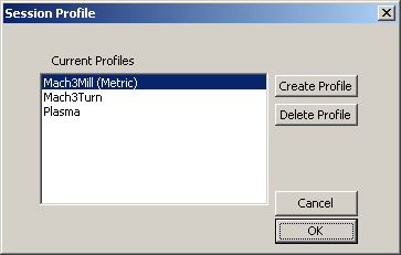
3. Select Mach3Mill (Metric). Click OK
4. Turn on the power on the 3040 and make sure that the E-Switch is not pressed.
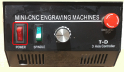
Note: The Power switch is ON (1) and the Spindle is OFF (0). The spindle is controlled by the program but the speed is not. Turn the spindle speed knob up to either max or near max. If you flip the spindle switch ON(1), the spindle will spin up. You only need to do this to test the spindle speed, or if your G-Code fails to turn it on and off automatically. The normal position for this switch is OFF(0).
Step 2 – Introduction to Mach3
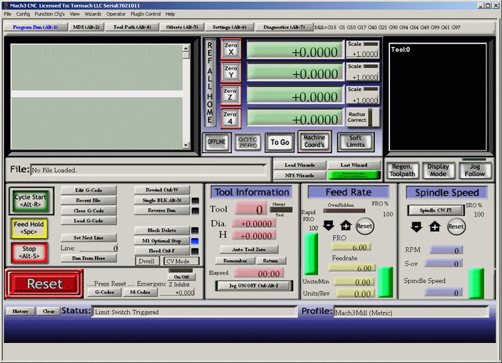
You should now see the Initial screen:
5. Clear any error messages in Status
The first thing is to notice the Red flashing border on the Reset button and Status message.
The example shows: “Limit Switch Triggered”. And the scrolling message says “Press Reset… Emergency mode Active. Emergency Z Inhibit”.

You may need to manually spin the knobs on the 3 axis to move the carriages off of the limit switches.
Keep clicking reset, and resolving the issues, until the status is clear of any messages.
The Border on the reset button should also be green.

6. Home the carriages
Click in the “REF ALL HOME” button.
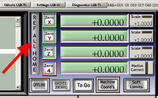
The 3 carriages will seek their home positions and the 3 buttons will go green and the position will show +0.0000.
Step 3 - Getting ready to mill your piece
7. Mount your piece on the milling table.
You need to be careful of
8. Move carriage to a new home position
Note that the travel limit switches are now is a “Dead Man” mode. If you accidentally drive the carriage too far and it trips a switch, the CNC will go into error mode and you will need to manually resolve.
To assist you in preventing this problem, enable the “Soft Limits” button.
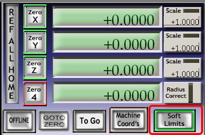
The behavior will now be that the controller will not allow you to go out of limits. You will hear a noticeable slowing down in the motion if you try to drive it too close to the edge.
Now, you can manually move the carriage to a new position, like the a new home position on the corner of your work piece.
The Secret Key => TAB. This will turn on/off the manual controls:
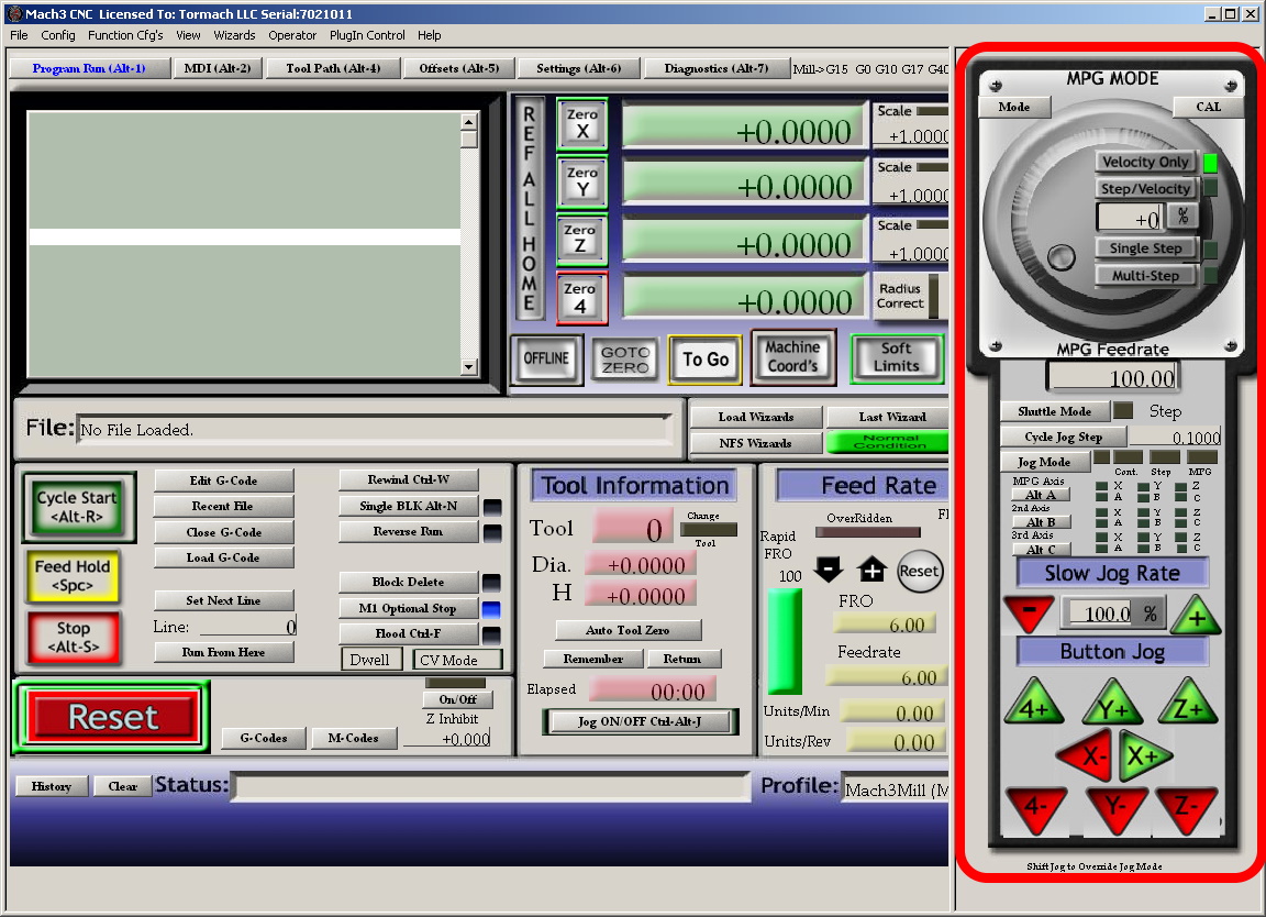
Note that Green is Positive direction and Red is negative.
Also, the direction of the arrows match the direction of the 3 axis (left => left, up => up, etc)
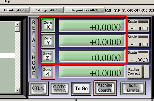
Once you have positioned the carriage in the perfect position, click on each of the “Zero X” buttons.
Step 4 – Determining the Bit height
The tool probe height sensor allow you to accurately control the height of your bit. To set the bit height, follow these steps:
9. Insert that bit of your choice in the chuck.
10. Attach the alligator lead to the bit.
11. Place the sensor puck under the bit.
12. Click on the “Auto Tool Zero” button. from the popup, select the height of the sensor. If using the puck then select the top value of 25.5. If using a thin strip of metal such as a utility knife blade, use the second entry (2.00??). Note that these numbers can be configured and may be tweaked by users who have tuned it for perfection. More on this to be documented later.
NOTE: Get ready to hit the E-Stop if things go badly. This can damage bits and such. The Z axis will slowly drop down until it makes contact with the puck, and then retract a short distance. Note that the distance that it retracts can be adjusted, but the default is 1.27mm.
The Z axis should now have automatically been set to your work surface. All G-Code references should now use this height as its reference. Positive values will raise the bit above the material and negative value will cut material.
Note as well: This sensor can also be used for edge sensing. This will be investigated in future.
Step 5 – Loading and editing your G-Code
13. The next step in milling anything is to load a G-Code file.
Note that instruction on how to create a G-Code file is beyond the scope of this tutorial and is up to you. You can use programs such as Fusion 360 or a simpler program such as Easel
- Beginners can get started with Easy CAM Guide, which explains how to create milling files using Easel's browser-based CAM. (See this sample Easy CAM: Creating a Milling File with Easel until we get our own added)
- Advanced users can learn more about CAM with Autodesk Fusion 360 by checking out this Fusion CAM writeup.
I have documented a very very simple sample in order to demonstrate the concepts of how to use the tool.
To load a g-code file, simply click on “Load G-Code” button.
Now that you have loaded your G-Code, I would like to run you through what I have learned about the dialog's.
- By clicking on the G-Code Dialog box, you can then scroll up and down the file. It appears that you cannot edit on the screen, but you can start selecting some other nifty controls within the file.
- To edit the code, you click on the “Edit G-Code” button. This will open the file in a text editor. When you close the file it will automatically load back into Mach3
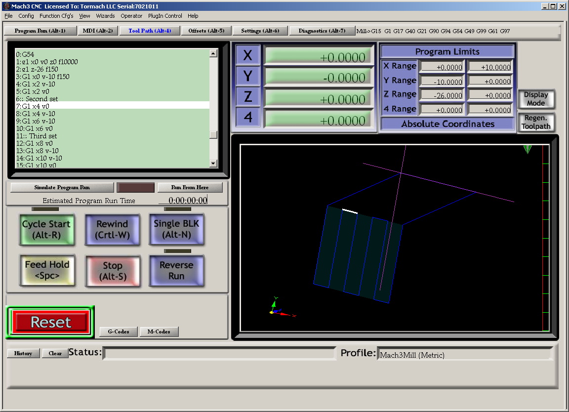
- Also note if your click on the “Tool Path (Alt-4)” then you can visualize the cut path on each line of the G-Code file.
(The sample image shows the tool path after I moved the image slightly to view the Z axis. Do this by click and hold the moue button on the view window and then moving the mouse slowly.
Notice that the line highlighted in the G-Code dialog box is also highlighted in the tool path window.
Important Note: in the sample, on line 2, it says to go to Z-26 (G1 Z-26 F150). This was what I entered before I understood how to use the height sensor properly. This is using a reference of Z as Zero after using the buck to sense the height, but then I incorrectly reset the Z height to zero manually.
This will be updated with a proper graphic and instructions once we figure it out.
Meanwhile, set your code to a very small number (G1 Z-0.5 F150) and test it first before you break a bit.
